Admission and analysis of time information in video pictures
Part 2
 Seite in Deutsch
Measurements with the video module SK-1004XC/SO + Time-Inserter KIWI-OSD
The KIWI-OSD developed by Geoff Hitchcox from Christchurch in New Zealand can receive the world time UTC using an external Garmin GPS modul 18 LVC. With this equipment then the exact time information can be faded in into a video signal.
For the measurements the following components were used
Video cameramodul SK-1004XC/SO with 1/3 Zoll Sony EXview CCD-Sensor ICX255AL
Xpert V-Stream videograbber USB2.0
Notebook Dell Centrino
Time-Inserter KIWI-OSD
GPS-Modul Garmin 18 LVC
Oscilloscope
A goal of the measurements
Control of the correct connections of time and picture information in the video half-images
Collection of the point
of exposure time of the camera module SK-1004XC/SO
Collection of the exposure duration in a videofield (half-image).
Description of the measurement setup
Camera module, KIWI-OSD with GPS, Videograbber and Notebook were connected as usual and put in operation. In a small additional circuit with the component LM1881 from the video signal a switching signal between Odd and Evenfield was
produced. During the first half-image with the odd lines this signal is on High level and in the second half-image with the even rows on Low level. Thus a square wave signal with 25 cycles per second results in the case of a PAL video signal. This square wave signal was measured with a analog oscilloscope and displayed on the screen. The time base at the oscilloscope was 10ms/DIV. To keep the beam afterglow as short as possible the brightness of the beam was adjusted as low as possible. This screen image then could be taken by the video module.
In order to get an accurate allocation to the start of each UTC second, KIWI-OSD was placed above the oscilloscope in the field of view of the video camera . Now blinking LED in the box of KIWI-OSD at the beginning of each UTC second was clearly visible on video fields. The LED was controlled directly by the 1PPS output of the GPS. The 1PPS output signal of the GPS receiver was adjusted to a signal period of exactly 100ms High and 900ms Low.
The measurement is documented in six each other following pictures
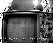
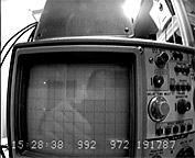
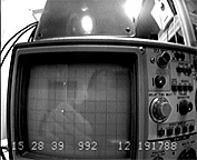
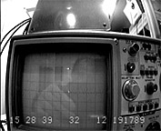
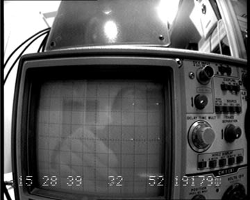
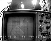
The following pictures come directly from the video module. In the big image on the left side always two half-images are overlaid to one picture. This procedure is very well recognizable by the inserted times and field numbers. On the right side both half-images are displayed separated.
E_Field: 15:28:38,952 - 15:28:38,972   #191786
O_Field: 15:28:38,972 - 15:28:38,992   #191787
Expos:   last 2 ms in every field
Image:   #191786 + #191787 superimposed
E_Sync:  15:28:38,952   \_ fall
O_Sync:  15:28:38,972   _/ rise
E_Sync:  15:28:38,992   \_ fall (beam visible)
LED:     in both fields OFF
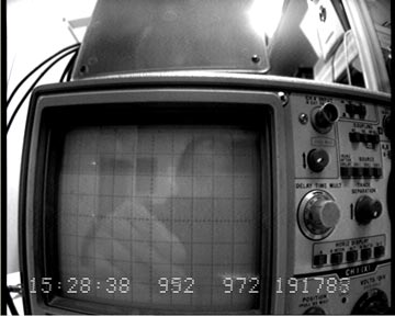 |
#191786 and #191787
 |
|
E_Field: 15:28:38,992 - 15:28:39,012   #191788
O_Field: 15:28:39,012 - 15:28:39,032   #191789
Expos:   last 2 ms in every field
Image:   #191788 + #191789 superimposed
E_Sync:  15:28:38,992   \_ fall
O_Sync:  15:28:39,012   _/ rise (beam visible)
E_Sync:  15:28:39,032   \_ fall (beam visible)
LED:     in both fields ON
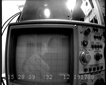 |
#191788 and #191789
 |
|
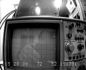
E_Field: 15:28:39,032 - 15:28:39,052   #191790
O_Field: 15:28:39,052 - 15:28:39,072   #191791
Expos:   last 2 ms in every field
Image:   #191790 + #191791 superimposed
E_Sync:  15:28:39,032   \_ fall
O_Sync:  15:28:39,052   _/ rise (beam visible)
E_Sync:  15:28:39,072   \_ fall (beam visible)
LED:     in both fields ON
 |
#191790 and #191791
 |
|
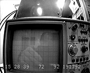
E_Field: 15:28:39,072 - 15:28:39,092   #191792
O_Field: 15:28:39,092 - 15:28:39,112   #191793
Expos:   last 2 ms in every field
Image:   #191792 + #191793 superimposed
E_Sync:  15:28:39,072   \_ fall
O_Sync:  15:28:39,092   _/ rise
E_Sync:  15:28:39,112   \_ fall
LED:     E_Field ON + O_Field OFF (Dur. 100ms)
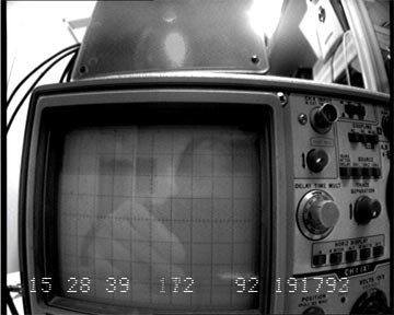 |
#191792 and #191793
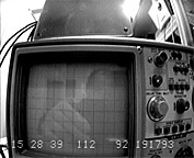 |
| LED is lit only in the first half-image so one can see it as dimmed. |
|
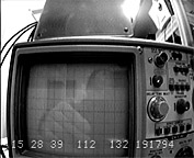
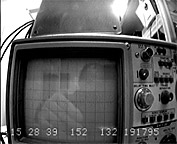
E_Field: 15:28:39,112 - 15:28:39,132   #191794
O_Field: 15:28:39,132 - 15:28:39,152   #191795
Expos:   last 2 ms in every field
Image:   #191794 + #191795 superimposed
E_Sync:  15:28:39,112   \_ fall
O_Sync:  15:28:39,132   _/ rise
E_Sync:  15:28:39,152   \_ fall
LED:     in both fields OFF
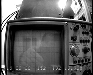 |
#191794 and #191795
 |
|
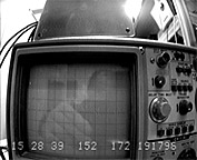
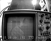
E_Field: 15:28:39,152 - 15:28:39,172   #191796
O_Field: 15:28:39,172 - 15:28:39,192   #191797
Expos:   last 2 ms in every field
Image:   #191796 + #191797 superimposed
E_Sync:  15:28:39,152   \_ fall
O_Sync:  15:28:39,172   _/ rise (beam visible)
E_Sync:  15:28:39,192   \_ fall (beam visible)
LED:     in both fields OFF
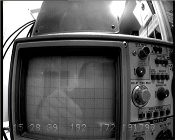 |
#191796 and #191797
 |
|
Results of measurement and conclusion
1.) KIWI-OSD assigns each half-image always accurately the correct recording time as time insertion. It is essential that an event appears in the picture if it occurs between the inserted starting and stop time.
2.) The camera module SK-1004XC/SO exposed in this measurement in well lit environment always at the end of each half-image (Field) for a duration of around 2ms. Events occuring only in the first 18 ms of a half-image could not be recorded. That is very clearly visible on the oscilloscope beam.
Following measurements with a new by me in June 2006 developed device, the Video EXposure Analyzer (VEXA), brought more accurate values with a higher timing resolution.


